NIKOLA TESLA'S ENERGY FROM SPACE
PATENTS ABOUT RECEIVE RADIANT ENERGY
TESLA'S ARTICLE: 'The Problem of Increasing Human Energy'
ELECTRIC GENERATOR (mechanical vibration to electric convertor)
TESLA'S ENERGY FROM SPACE SYSTEM
LORD KELVIN DROPPER SYSTEM AND TESLA'S TRANSFORMER CONVERTER
ILUMINATION SYSTEM AND STRANGE PHENOMENA
HIGH VOLTAGE STATIC TRANSMITTER AND RECEIVER
NEW ENERGY SOURCE (AIR ELECTRICITY)
NEW UNDERSTANDING OF DIRECT CURENT PHENOMENA (MOST IMPORTANT)
THUNDERSTORM HYDROGEN GENERATOR
SPARK GENERATOR (EMBRIO OF IMPORTANT DEVICE)
ROTATING SPARK GENERATOR (WORKING DEVICE)
ELECTRO-MAGNETIC GENERATOR WITH PIPE DESIGN
UNLIMITED SOURCE OF CLEAN ENERGY
.
.
.
.
.
.
.
.
.
.
.
.
.
.
.
.
.
.
.
.
.
.
.
.
.
.
.
.
.
.
.
.
.
.
.
.
.
.
.
.
.
.
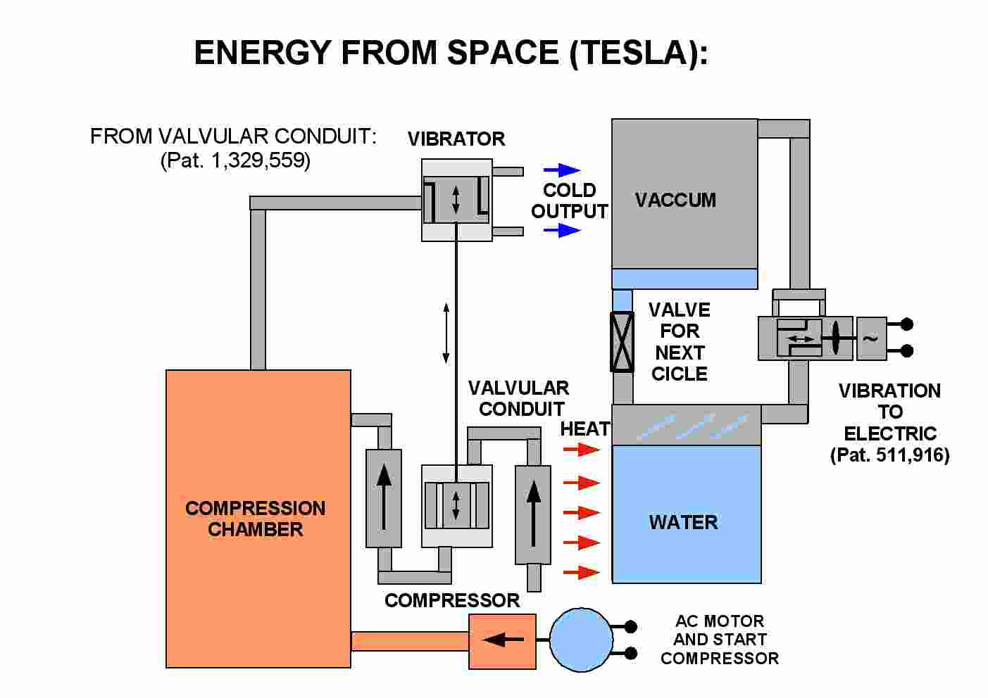
This is my modification of Tesla system explain in patent 1,329,559 'Valvular conduit'.
His sistem for compressing air is heat generator too. Pressure of air can be reuse for vibrating, in cicle.
This system can be modify for modern heat pump design, where attenuation can be replace with vibrator. This vibration can be convert in electricity and for charging battery.
Timer can charge battery in night, and converter can in day supplay heat pump.
Heat on attenuator is reuse for charge and this system use less electric power, and use night power (less expense)
How much COP can be of this type heat machine?
.
.
.
.
.
.
.
.
.
.
.
.
.
.
.
.
.
.
.
.
.
.
.
.
.
.
.
.
.
.
.
.
.
.
.
.
.
.
.
.
.
.
ELECTRIC SPARK PUMPING SYSTEM:
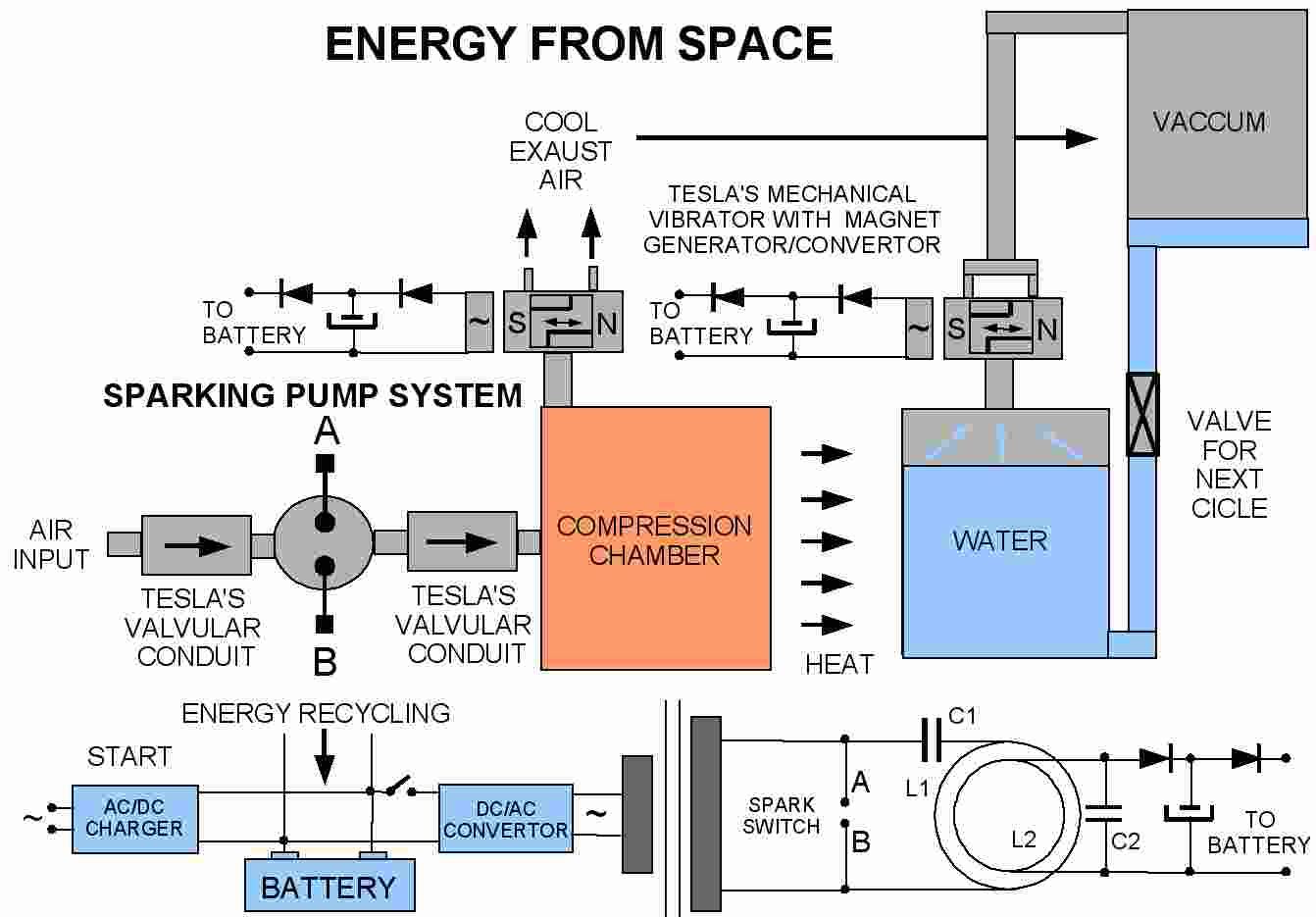
This is my theoretical design, and I did't build this yet:
1. Pumping air with Tesla transformer and with sparking place. Spark between two Tesla's valvular conduit.
2. Heat converting with water/vaccum steam. Mechanical to electric steam pressure conversion with Tesla's mechanical oscilator.
3. Recycling high frequency, pressure energy, and heat energy.
.
.
.
.
.
.
.
.
.
.
.
.
.
.
.
.
.
.
.
.
.
.
.
.
.
.
.
.
.
.
.
.
.
.
.
.
.
.
.
.
.
.
Principle of free energy from space is simple. Equation for air say: when temperature go up, volume go up (if presure and mass are constant)
Solar energy from Sun can do this for free.
It can be extract for free (oposite process)
When compress air we extract that energy (mechanical energy is need).
When uncompress air we sucking energy from space with cooling efect (mechanical energy come back, like from mechanical spring).
NEVER CONVERT THIS MECHANICAL ENERGY TO HEAT! (like in standard heat pump) Recycle it!
That is secret for free clean energy source.
.
.
.
.
.
.
.
.
.
.
.
.
.
.
.
.
.
.
.
.
.
.
.
.
.
.
.
.
.
.
.
.
.
.
.
.
.
.
.
.
.
.
Patents about receive radiant energy:
(this is copy from Tesla's transiver part of my web pages)
1: 685,957 'Apparatus for the Utilization of Radiant Energy'.
2: 685,958 'Method of Utilizing Radiant Energy'.
Principles for understanding in this patents are simple. When solar or other energy photons comes to plates elevating in air, it generate current in capacitor which is connecting to earth (grounded) plate.
Why? We have high potential between stratosphere and Earth. Some current are always here, because of that. High energy photons or particles ionize and plate became source of energy.
Capacitor must be the best, without self-discharge.
It looks like little source of energy.
But what will be if we virtual increase surface of plate with ionize air around plate with source of X-ray or UV-ray or other? Sun UV waves absorb when ozone is here.
Is Tesla thinking about using this system near his high voltage transmitter, which generate ionization around, and with this principle collect high Sun energy, with this virtual high surface solar panel?
It need more experiments, and maybe this low energy solar collector, can become high free energy source.
Just a thoughts!
.
.
.
.
.
.
.
.
.
.
.
.
.
.
.
.
.
.
.
.
.
.
.
.
.
.
.
.
.
.
.
.
.
.
.
.
.
.
.
.
.
.
The work temporarily interrupted was taken up anew, and soon I had in a fair state of perfection the engine which I have named "the mechanical oscillator." In this machine I succeeded in doing away with all packings, valves, and lubrication, and in producing so rapid a vibration of the piston that shafts of tough steel, fastened to the same and vibrated longitudinally, were torn asunder. By combining this engine with a dynamo of special design I produced a highly efficient electrical generator, invaluable in measurements and determinations of physical quantities on account of the unvarying rate of oscillation obtainable by its means. I exhibited several types of this machine, named "mechanical and electrical oscillator," before the Electrical Congress at the World's Fair in Chicago during the summer of 1893, in a lecture which, on account of other pressing work, I was unable to prepare for publication. On that occasion I exposed the principles of the mechanical oscillator, but the original purpose of this machine is explained here for the first time.
In the process, as I had primarily conceived it, for the utilization of the energy of the ambient medium, there were five essential elements in combination, and each of these had to be newly designed and perfected, as no such machines existed. The mechanical oscillator was the first element of this combination, and having perfected this, I turned to the next, which was an air-compressor of a design in certain respects resembling that of the mechanical oscillator. Similar difficulties in the construction were again encountered, but the work was pushed vigorously, and at the close of 1894 I had completed these two elements of the combination, and thus produced an apparatus for compressing air, virtually to any desired pressure, incomparably simpler, smaller, and more efficient than the ordinary. I was just beginning work on the third element, which together with the first two would give a refrigerating machine of exceptional efficiency and simplicity, when a misfortune befell me in the burning of my laboratory, which crippled my labors and delayed me. Shortly afterward Dr. Carl Linde announced the liquefaction of air by a self-cooling process, demonstrating that it was practicable to proceed with the cooling until liquefaction of the air took place. This was the only experimental proof which I was still wanting that energy was obtainable from the medium in the manner contemplated by me.
Nikola Tesla's system explain in patent 1,329,559 'Valvular conduit' has explanation for build such machine. Mechanical vibrator and valvular conduit with mechanical compressor is the secret for free energy heat machine.
.
.
.
.
.
.
.
.
.
.
.
.
.
.
.
.
.
.
.
.
.
.
.
.
.
.
.
.
.
.
.
.
.
.
.
.
.
.
.
.
.
.
Electric Generator (mechanical vibration to electric convertor):
511,916 'Electric Generator'.
It has three basic elements:
1. mechanical vibrator
2. air spring
3. electric part
Good thing of that machine is that on diferent presure, vibration can be constant (because of air spring).
Another modification of generator has condenser in resonant vibration with mechanical.
Bifilar winding from another Tesla's patent is posible replacement of that condenser (just my thought).
Understanding this principles is very important, for creating some 'free energy' machine, based on Tesla's ideas.
Maybe this mechanical system is best aproach for that achievement.
This kind of heat machine convertor, in combination with some hybrid car, will improve car range (because of about 70% heat wastage), and can add ambient heat energy to car usage too.
For now, I just collect ideas...
You can see it here:
.
.
.
.
.
.
.
.
.
.
.
.
.
.
.
.
.
.
.
.
.
.
.
.
.
.
.
.
.
.
.
.
.
.
.
.
.
.
.
.
.
.
TESLA'S ENERGY FROM SPACE SYSTEM:
This is closed loop system, based on Tesla's words, and my thoughts. Input is heat energy, and output is electric energy.
.
.
.
.
.
.
.
.
.
.
.
.
.
.
.
.
.
.
.
.
.
.
.
.
.
.
.
.
.
.
.
.
.
.
.
.
.
.
.
.
.
.
ENERGY FROM SPACE (OR RAIN) WITH LORD KELVIN DROPPER SYSTEM AND TESLA'S TRANSFORMER CONVERTER:
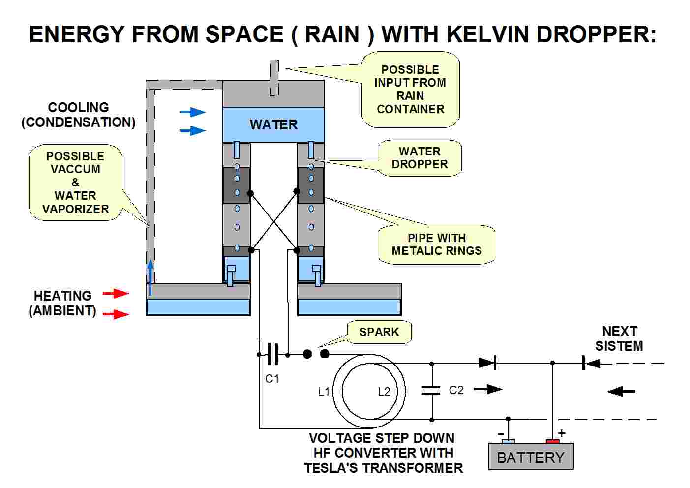
Lord Kelvin has found some embryo of simplicity for electric conversion. Drops of water make static electricity with four metallic pipe with cross connection. Tesla's transformer (high frequency) can step down this high voltage. All parts of machine are light. With this machine can convert raining on roof to electricity. It is first possibility, and the other can be (just a thoughts) with water/vacuum closed loop system. It can convert ambient heat (or car heat for hybrid car battery input). It need more investigation, and real machine and energy measurement. More than one system can be add for greatest energy output which improve waiting time for next spark.
Best effect is with destilize water, but work with other too. Which part will become positive, and which negative is random, and when start, it become cumulative process. Gravitation, water 2 H+ and OH-- is energy input here. Electric force and gravity force try to make balance, and before spark start, water try flying up.
.
.
.
.
.
.
.
.
.
.
.
.
.
.
.
.
.
.
.
.
.
.
.
.
.
.
.
.
.
.
.
.
.
.
.
.
.
.
.
.
.
.
I am so excite with this device. I will write in my mind: October 2007. It will maybe become something great (for make or wireless receive energy).
This device is so simple, and all my investigation will go to this direction. Don't forget to share this knowledge.
I start with coil design, and wire (like antenna). Capacity was 25 microF/400V, and some energy was come. Lot of experiments, and energy become greatest without inductivity. I was not sure that energy is from some radio station, because system was on 1 m of wire (like antenna). In my mind come Tesla's experiment, and I try with aluminum foil, and energy become greatest. Than I try with some old build foil with greatest area. I was sure that it is not radio station. It is forget Nikola Tesla energy source ( my modification of his receiver), and his DC design ( with X-rays or others ) become AC design (with greatest output if source is greatest than diodes barriers), and new possible source of energy is here (if exist in HF form).
I test charging capacitor with ground and wire (1 m) in interval of 5 minutes, and it was around 8 V in capacitor. Only 4 diodes, capacitor, wire and ground. When I put 30cm x 50cm Al-foil, in 5 minutes it charge on 11 V. When I put 1m x 1m Al-foil, it become 30 V in 5 minutes. It is like Tesla's plates with capacity and ground (I use water pipes grounding), modify with diodes (1N4148). I didn't try yet different diodes (because HF expectation). This device is first useful form, and need more experiment, but I have good filling. I will put this on my web, because I don't wont that mankind lose it if something happen to me. This web is my diary.
Diodes has voltage limit, and final design, with some discharge system must be designed with that in mind. This is embryo of something beautiful. Free energy?
But is it free energy? I detect some strange signal from my oven (this electric oven is just on greed, and don't work). It has some device for spark ignition. Or is it from electric grid? This 'free energy' device is maybe just receiver for some field. It need more investigation.
Tesla use something similar, with rotating switch for receiving ground signal. This 'primitive' switch has advantages: no diodes barriers. Possible use of LC circuit with some auto amplification (Q=2PIf/R factor) will bypass this barrier problem, but it reduce frequency to resonant.
.
.
.
.
.
.
.
.
.
.
.
.
.
.
.
.
.
.
.
.
.
.
.
.
.
.
.
.
.
.
.
.
.
.
.
.
.
.
.
.
.
.
SINGLE WIRE TRANSMISSION LINE:
I will try to explain 'one wire transmission line'. I remember when I was child, I was build first sound transmitter with two plastic cups and cord in between. My friend was talk on one side, and I was listen (and opposite). If thundering do that with Earth, is it possible receive that signal? Flashing in ionosphere must have some effect in opposite charge (it is capacity system and it is on great charge and voltage).
This device will be like energy receiver, like cups when receive sound signal through cord line. Only electron movement is here, not mechanical vibration.
I see that barriers problem. Lot of signals exist in voltage form smaller than that 0.5 V barrier. I don't like mechanical switching, but it is possible solution.
If it can receive grid parasite energy, how much energy could be possible receive with 'no barrier' diode switch from Earth (thundering source)?
.
.
.
.
.
.
.
.
.
.
.
.
.
.
.
.
.
.
.
.
.
.
.
.
.
.
.
.
.
.
.
.
.
.
.
.
.
.
.
.
.
.
ILUMINATION SYSTEM AND STRANGE PHENOMENA:

This is from Tesla's papers "EXPERIMENTS WITH ALTERNATE CURRENTS OF VERY HIGH FREQUENCY AND THEIR APPLICATION TO METHODS OF ARTIFICIAL ILLUMINATION" which is delivered before the American Institute of Electrical Engineers, Columbia College, N.Y., May 20, 1891.
One part is specially occupy my mind:
"The ideal way of lighting a hall or room would, however, be to produce such a condition in it that an illuminating device could be moved and put anywhere, and that it is lighted, no matter where it is put and without being electrically connected to anything. I have been able to produce such a condition by creating in the room a powerful, rapidly alternating electrostatic field. For this purpose I suspend a sheet of metal a distance from the ceiling on insulating cords and connect it to one terminal of the induction coil, the other terminal being preferably connected to the ground. Or else I suspend two sheets as illustrated in Fig. 29 / 125, each sheet being connected with one of the terminals of the coil, and their size being carefully determined. An exhausted tube may then be carried in the hand anywhere between the sheets or placed anywhere, even a certain distance beyond them; it remains always luminous."
And here come interesting part:
"In such an electrostatic field interesting phenomena may be observed, especially if the alternations are kept low and the potentials excessively high. In addition to the luminous phenomena mentioned, one may observe that any insulated conductor gives sparks when the hand or another object is approached to it, and the sparks may often be powerful. When a large conducting object is fastened on an insulating support, and the hand approached to it, a vibration, due to the rythmical motion of the air molecules is felt, and luminous streams may be perceived when the hand is held rear a pointed projection. When a telephone receiver is made to touch with one or both of its terminals art insulated conductor of some size, the telephone emits a loud sound; it also emits a sound when a length of wire is attached to one or both terminals, and with very powerful fields a sound may be perceived even without any wire."
What is that electrostatic phenomena? Field between two plates are in alternate form, and insulate plate give spark. Why? Is it from some natural rectifier effect, or has some relation with Earth current from stratosphere? That Tesla's thoughts about 'cosmic ray' system, which work 24 hours/day come to my mind. I don't know that yet, and this need investigation. Charging capacitor from plates in air and ground is interesting. If in compressing air 'heat pump' system could make around 3 times more heat, is it possible extract more electricity from Earth capacitor system? Is it some electric sink, or just some rectifier effect from our high voltage alternating source? With that alternating high voltage we do something inside that earth capacitor (air), and this effect is maybe way to receive that energy. If it is not so, it is interesting effect, and it need more investigation. I did not noticed this effect before. I know lot of electricity phenomena, but I don't understand this one entirely. I will try to follow that spark.
.
.
.
.
.
.
.
.
.
.
.
.
.
.
.
.
.
.
.
.
.
.
.
.
.
.
.
.
.
.
.
.
.
.
.
.
.
.
.
.
.
.
HIGH VOLTAGE STATIC TRANSMITTER AND RECEIVER:
I start with little experimental system:
1. Two plates ( 0.5 m x 0.5 m )
2. HF transformer ( 12V / 8W car HF lamp ). I just get electronic from lamp with 1 transistor and ferrite transformer.
3. Grounding plate ( 10 cm x 15 cm ) with rectifier diodes and condenser ( 470 uF )
Input was 12 V and 0.25 A (it is around 3W, because it is without lamp). Two plates distance was 0.5 m and that little receiver plate was in middle. Voltage in capacitor going up around 1 V for 1 second, and around 1 minutes capacitor has 50 V. Energy is much less than from battery, but this system can transmit and receive energy. When I disconnect input energy, condenser charging going little up after discharge for few second. Why? I try without diode system, but it charge capacitor with low energy. I think that FET replacement for diodes will be good approach for low energy receiving.
Can be possible make car charging system without wire? On parking place? On the road, maybe? It need high energy testing. I am satisfied with this low energy experiment.
.
.
.
.
.
.
.
.
.
.
.
.
.
.
.
.
.
.
.
.
.
.
.
.
.
.
.
.
.
.
.
.
.
.
.
.
.
.
.
.
.
.
When I connect little middle plate to right plate, charging of condenser is greatest. It go to 100 V in 5 second.
It become standard 'one wire' transmition line. Because one plate is still in air and has only capacity connection to ground, energy in capacitor is less than input.
Input: U = 12 V, I = 0.25 A, P = U * I = 3 W. Charging capacitor on 100 V in 5 seconds give input energy E = P * t = 3*5=15 Ws (or J).
Output (energy in capacitor): E = 0.5 * C * U*U = 0.5 * 470E-6 * 100 * 100 = 2.35 Ws (or J; I more like Ws when work with electricity). It is around 6 times less energy than input consumption.
I am not done experiment with grounding second (left) plate, because of fast growing up of capacitor voltage. I have 400 V limit on capacitor, and I don't want burn capacitor (or diodes).
Interesting here is that high frequency voltage conversion. Tesla's 3 phase motor come to my mind, with 3 capacitor charging and discharging system (on 3 motor coils). It will need high power electronics, but it will work. Possibility of wireless car charging system is here.
If I discharge this system, after 1 day, it has 1 or 2 voltage on capacitor. Low level of free energy (natural or human source?).
.
.
.
.
.
.
.
.
.
.
.
.
.
.
.
.
.
.
.
.
.
.
.
.
.
.
.
.
.
.
.
.
.
.
.
.
.
.
.
.
.
.
This design is better approach. It has 2 capacitor (one more), but only 2 diode with half reverse barriers. This two capacitor has double voltage (In equation E = 0.5*C*U*U voltage is square function and capacity is not). When diodes will be replaced with FET (for remove barriers and synchronize with some frequency) it will need only two FET transistor. It will be simplest design.
.
.
.
.
.
.
.
.
.
.
.
.
.
.
.
.
.
.
.
.
.
.
.
.
.
.
.
.
.
.
.
.
.
.
.
.
.
.
.
.
.
.
NEW ENERGY SOURCE (AIR ELECTRICITY):
This is my new theoretical design. It is based on Tesla's transmitter/receiver. The base idea is use ionization path of Tesla's high frequency transformer, and that path for collecting direct current air electricity. I think that it is reason why I receive some charging, after stop of transmitting which I am write before. This system need thunder protection and discharge converters, but principle is clear to me. It is like use direct current for power supply on TV amplifier, with HF conduction in coaxial cable. High inductivity is use for split DC current from HF. More ionization (higher voltage of transmitter), will create greatest current. If backward wire is not grounded, capacity between elevated electrode and ground will be less, and air DC will not going through that path to ground.
Hermann Plauson (pat. 1540998) has work on that 'air energy' and he was use balloons for that purpose. Great clean energy is all around us. With Tesla's transformer, we don't need balloon. I am testing little system, and capacity charging is here. Energy is here. It is great discovery in my life. I share it with you. Thanks to Nikola Tesla for his work and thoughts.
SIMPLEST FORM DESIGN (proof of concept):
This is my first 'proof of concept' design. Transformer was 12 V and 3W input, and around 150 V high frequency output, with 0.5 x 0.5 m two plates. It was in my basement with concrete ceiling. Around 3 m difference between plates, and 1.5 m up the floor. Capacity was 25 uF, and it's voltage was going up to around 20 V for 30 second. Grounding was with wire to nail in tree in my garden. Start for charging was slow, and than speed of charging going up. Energy is less than input for HF transformer, but it is direct current (without any diodes). High inductivity was from 'fluorescent light' (one wire coil with Fe core) for DC/AC separation.
I think, here is right place to put this Tesla thoughts:
"Throughout space there is energy. Is this energy static or kinetic! If static our hopes are in vain; if kinetic - and this we know it is, for certain - then it is a mere question of time when men will succeed in attaching their machinery to the very wheelwork of nature." (Nikola Tesla)
I think that 'time when men will succeed' is come!
TESTING DESIGN WITHOUT SEMICONDUCTORS (proof of concept, add this comment on 27. April 2008.):
I build simple Tesla high frequency transformer without any diode or transistor switch. I am testing existence of ground direct current, when in the setup is only alternating current. Output spark is around 2-3 mm, and coil is just 20 turns ( d=1mm )around 1 turn build from Cu pipe ( D=80cm, d=8mm ). Coil has problem with sparking between turns, because of using just 7 circular plastic space bar. Between them is around 25 cm of distance, and some wires become to close, and spark. Coil is just my circular 'driver' design. It need adding plastic element, but it is hard to do that, because all of part is glued with hoot glue pistol. I did not put spiral extra coil in the middle yet. This simple (low energy, because of neon 4 kV transformer) has capacitor build with glass plates (20cm x 20cm, 6 of them, with aluminum foil and power tape insulation around capacitor), spark gap and no resonance (it is not important, because of high k on that first 20 turns (all around primary turn). Extra coil will magnify voltage output, but it will be my next setup.
Higher voltage, higher that direct current effect to ground will be (I think). I work in basement, use ground on water pipe, with two plates (1m x 0.5m, aluminum foil on paperboard). I don't expect too much, just a proof. I put filter (just before ground capacitor). I don't want that high frequency going to ground. It is just improvisation (neon coil with core). It has high inductance, but its self capacitance is not good for that purpose. This is just for testing. Capacitor between ground and that 'filter' is 25uF/400V. Differences between upper picture is that I put filter and capacitor on lower voltage part on secundary coil (start of turns). Maybe correction on upper picture will be best for understanding. But output voltage on transformer without ground is relative.
When I start this transformer, it need around 60 second for 1 V on that capacitor. If I put 3 capacitor in series, charging is faster (because of 1/3 of C). Direct current is here, with few mm of spark. I think that it need higher voltage on elevated plates. It is just electric 'pump'. It need recycle of input energy, and direct current energy from plates is just side-effect.
I keep in my mind that some vacuum bulb, will produce high 'dark ray'. If that rays hit plates, that direct current effect will add energy to grounding capacitor. Maybe this kind of recycling is possible. If we put grounding capacitor near vacuum bulb, it will charge immediately (without plate, on his one end). Every conductor will be attracted to bulb, and human hand will have push feeling. It need investigation with better equipments. Measure of X-ray, or others is important. Be careful here...
Some devices with deuterium and crystal (on changes of temperatures it produce high electric voltage, like piezoelectric crystals) can generate neutrons (fusion of hydrogen-deuterium). It is known neutron generators. Tesla's light tube in high vacuum is high accelerator too. Tesla was stopped that experiment, because of danger rays. But where high energy is, always danger exist too. I think, that with vacuum bulb, and right material in the middle, it material can become radioactive, and plate/capacitor/ground system can make energy from radioactivity too. It is just possibility. I would like make energy without that danger part. Stratosphere is full of charge, and all around us are cosmic rays. Tesla has found that direct current energy when he was experimenting with high voltage and high frequency transformer. Maybe some transistor based battery device, will do 'pumping', for that purpose. We need high frequency, but high voltage is important. Maybe current could be very low (low 'pumping' energy). It is like heat pumping system, where pressure is voltage here. Higher pressure, higher extra heat.
NEW UNDERSTANDING OF DIRECT CURENT PHENOMENA (MOST IMPORTANT):
After lot of experiments, and strange charging and no-charging (frustrating) results, I was finally found cause of that. This simplest form of Tesla's transformer, with lowest energy input, without extra coil was my starting point. Output spark is around 1 cm maximum, and secundar is not danger, and is good for testing. Primary part is danger, but it is well know for that kind of machine.
I see here some strange phenomena. On starting of this experiment, I was using two plates, but charging of capacitor was low, and sometimes zero, sometimes around 10 V with 25uF. That strange direct current make me mad. Why is it so weak, and not always here. And I found cause. When output coil has some spark, direct current is here, when spark don't exist, no current. Two plates was out of my basement, around 1 m from ground, and about 15 m between them. Every time when I was touch 'hot' plate, and it was sparking to my fingers, capacitor was on some direct current charge. I just try spark between plate and some grounded metallic construction. DC charging was here. 50 V on 25 uF in 1 minutes was great improvement. I change capacitor with 470 uF, because I don't want danger voltage in it. Charging of capacitor was very good. Maybe spark work like some diode valve? I don't recycle energy from ends of second plate (no sparking Al plate 0.5 x 0.5 m). For now I just testing that interesting direct current phenomena.
Another idea was coming to my mind. Why I need 'hot' plate? When spark exist, because of high voltage, it going to ground. Best ground is where capacitor is on ground. I was try that before, but no DC charging voltage. But I did not try with spark. I just tray with connection to ground. When I disconnect wire from 'hot' plate, and make connection to ground wire (spark between two wire, around 5 mm), capacitor of 470 uF is going to 20 V in 20 second. Second (no 'hot') plate was in basement, because of raining that day which start on the evening. It need experiment with outside no-hot plate, its area and elevation. I am satisfy with this results. I just understand more than before. I must note that when spark is around 8 mm, sometimes charging going to opposite direction. Because electrolyte capacitor, it is not good, but they are in good condition (for now). Better charging was when spark was good and sparking wires was point to point. That part need more experiment too. But SPARK MUST EXIST. Secundar is not in short-cut condition, because one part is not grounded. I think that high filter is important too. I just work with some 100 turns on ferrite (no, no, it was turns around permanent magnet, which I found around). I see some low sparking in that coil. It need better HF filter with ferrite, and without sparking. But I must stop, because it is too late, and my family need me too...
Something strange is in this charging polarity. Most of time, capacitor plate is positive, but sometimes become negative, or voltage going little down. Is it Tesla's cosmic ray energy? Particle with lot of charge of one direction, and sometimes opposite? Capacitor's voltage going up, sometimes down, and up again. If some particle are responsible for charging, here are more of one sign, and less with another. More energy will be here if charging is only in one direction (car can pass more if going to one direction, and not 10 m forward, and 2 backward, and then forward...). I try with diode 1N4007 (around 1000 V breakage), and I was expect break, because that 'no-hot' part of transformer has around 1 mm sparking ('hot-part' has 10 mm). This maybe can be danger for capacitor too, but for now, they work very well. Before charging of capacitor, some perfect diode bridge with high opposite breakdown voltage and low barrier voltage when current going to charging direction, will be perfect. It will be interesting to see two capacitor of the same capacity, and their voltage, after some time of charging. I think, that I am found Tesla's 'cosmic ray' energy. Maybe some tube diodes will help here (I don't know, because I always work with silicon diodes. Maybe some series of diodes will work, but here is just low energy transformer for testing purpose. If Tesla's transformer has more power input, standard diodes will always break (who knows how much energy is here?) Capacitor must be for alternating current if it work without diodes (like in one phase AC motor). If I find some rectifier system, than it will represent real energy output. For now, voltage on capacitor is just some sum of two direction energy. Maybe my new approach, with electrolysis of water, and then fire on with turbine/generator, will be simple replacement of capacitor/diodes system, for great energy output. I am just open this old Tesla's energy secret. I give credit to him... He was the first, and we owe to him that credit.
After lot of experiments, I think that main source of charging capacitor, is from sparking place. Plates on air are not so important (when are low elevated). I just eliminate them, and charging was the same. Maybe one plate can be between ferrite and capacitor (I didn't try high elevation). When sparks are in vertical discharging direction, it has low effect of charging capacitor, but horizontal has more than 100 V on 10 uF in 5 seconds. Because of random charging (maybe from opposite charge of cosmic rays?), some rotating switch will be nice here. First, after interval of charging, second little middle place, and than third some diode bridge and discharge to some greater capacitor, or battery. Bridge will correct that random charging, and it will protect diodes from break too. Voltage on first capacitor will depend of rotating speed, and passing energy. Maybe discharge to battery will be bast approach.
.
.
.
.
.
.
.
.
.
.
.
.
.
.
.
.
.
.
.
.
.
.
.
.
.
.
.
.
.
.
.
.
.
.
.
.
.
.
.
.
.
.
THUNDERSTORM HYDROGEN GENERATOR:
This is just theoretical design. Don't try build this system at home. But, some power plant, on right (thunder-place) could be build. This could be protection from uncontrolled thunders discharge. This idea is for making hydrogen from thunders discharge.
It use electrlytic device (I explain detail on 1. page of this web). Electrolyte is sodium-bicarbonate, and has stainless steel electrodes, with design for split hydrogen and oxygen. Voltage of thunder is very high, but current is too. This hydrogen/oxygen power plant need lot of cells in serial connection. Every thunder discharge will make hydrogen and oxygen. Combustion of this gases could make standard electricity. Compression is well known method.
.
.
.
.
.
.
.
.
.
.
.
.
.
.
.
.
.
.
.
.
.
.
.
.
.
.
.
.
.
.
.
.
.
.
.
.
.
.
.
.
.
.
SPARK GENERATOR (EMBRIO OF IMPORTANT DEVICE):
I am build some interesting device based on Electrophorus' device. This old device for making static electricity is come to my interesting. I am build 60 cm X 60 cm device, from simplest part of 'Stirodur' material. On downside i put Al-foil. I cut another plate in circular form (Stirodur again) around 50 cm diameter, and put Al-foil on it. Because I didn't want build some handle, I just glue Al-foil on it, not in circular form, because of places for hand.
Standard device need grounding of the bottom foil. Device need activation and with some clout it need rubbing on the start. When put circular stirodur with Al-foil on that plate, and touch it with hand, spark will come. It is not danger spark. When that circular plate move up, after touch another spark will come. It could be repeat and repeat again. I ask myself: "Why I must touch that upper plate when come close to insulator? If downside plate must be on grounding point, my body simulate that grounding to." I make some hole in the middle of first (not moving) plate, and with some screw, I make connection with grounding Al-foil. I don't need grounding. It don't need touching with hand.
When I put upper plate on that place, spark come to that middle point connection (this replace need for my hand touching). When I move upper plate up, this moving plate have some charge. Hand will discharge it, or moving to some grounding part (water pipe). Spark with my device is around 2-5 mm. When move down, and plates touch each other, spark come to middle connection, and when move up, spark is here to.
I will tell you what is my problem in understanding of this device. Standard explanation is that this is capacitor, and when you move plate from it, energy must make some electric voltage, because capacity going down. I see some problem here. In my modification, middle point connection make short circuit with that two plates. What energy is in short circuit capacitor? This short circuit system is on the same potential, which is - or + (depend of rubbing clout). But if I connect with ground, it is on zero potential. Both plates are on grounding, because of that screw in the middle of not moving plate. If we move upper plate again, spark is here. I think, this device need some different explanation. I am not satisfied with standard 'capacitor' explanation.
I think that here is some phenomena like in homopolar generator, where magnet field can be glued on rotating Cu plate, and with rotation, energy will come out, and relative movement of plate and magnet is zero. It not need cutting field for induction. I think that I look here some similar effect, but with electric field. Here I see device for making electricity from some electric charge of one direction in place in space. It look like 'space' energy from charge. It is simplest form of electric generator that I know. I must say that I try add more Al-foil (make circular on upper part), but spark was less (maybe corona discharge is problem, because my hand was 2 cm close to AL-foil, and when I come to discharge point, charge is gone to my hand).
When I put this device overnight, and come in the morning, spark is here too, but it is not great like in first start after rubbing. I think that this device is possible to be in connection with stratosphere potential, but maybe is just in connection with charge in space. Is it some sink device? Tesla's insulated plate on air come to my mind. Maybe his patented device need some excitement to be useful? In standard form, I didn't make lot of electricity from his device. But my replica didn't have perfect insulation. Is Tesla found some device with not moving part? He was disappointed with Marconi court problem, and maybe he was smart here, and not say all detail. But his device has capacitor and switch, and cosmic ray excitement. But, wind can generate moving to. Spark could be converted to frequency with coil, and collected in low voltage form with some spiral Tesla coil transformer in opossite transforming direction.
It will be good if every school will have this device, with my little modification for automated generation of spark, without grounding connection. This is proof of principle device, and basic form was make few hundred years ago from Volta and others. You mast have one in your hand, if you are free energy researcher. I think that here is something important for mankind. My daughter like playing with this toy. But we know that it is not just toy. Don't use 'smell' glue, use paper glue, because of melting of Styrofoam plate. I use just standard paper tape-glue. I build this device in about half of hour. I will try to make with different insulator (some people talk about Teflon like good one) and with different thickness. My Stirodur plate was 2 cm thick.
Update thoughts (after some experiments):
I connect capacitor and voltmeter with two plate (mV measurement). When upper plate going up, voltage going up, if going down voltage going down. If upper plate movement is in horizontal direction, changes of voltage is here. If upper conductor will oscillate, voltage will oscillate too.
Best effect will be with Teflon insulator. Greatest area, greatest energy generation will be. I think that Tesla's device need insulation for work, and that 'upper plate' can be replaced with ground connection. But insulated plate in the air need some change in distance between air insulated plate and grounding virtual plate. But in Tesla system, insulated plate is on constant height. I think that capacitance around the plate can change with ionization beam of X-ray, UV-ray or cosmic ray. Because of that, here is possibility that his device will work. If someone will try experiment with that, I suggest Teflon insulation of insulated plate in Tesla's system.
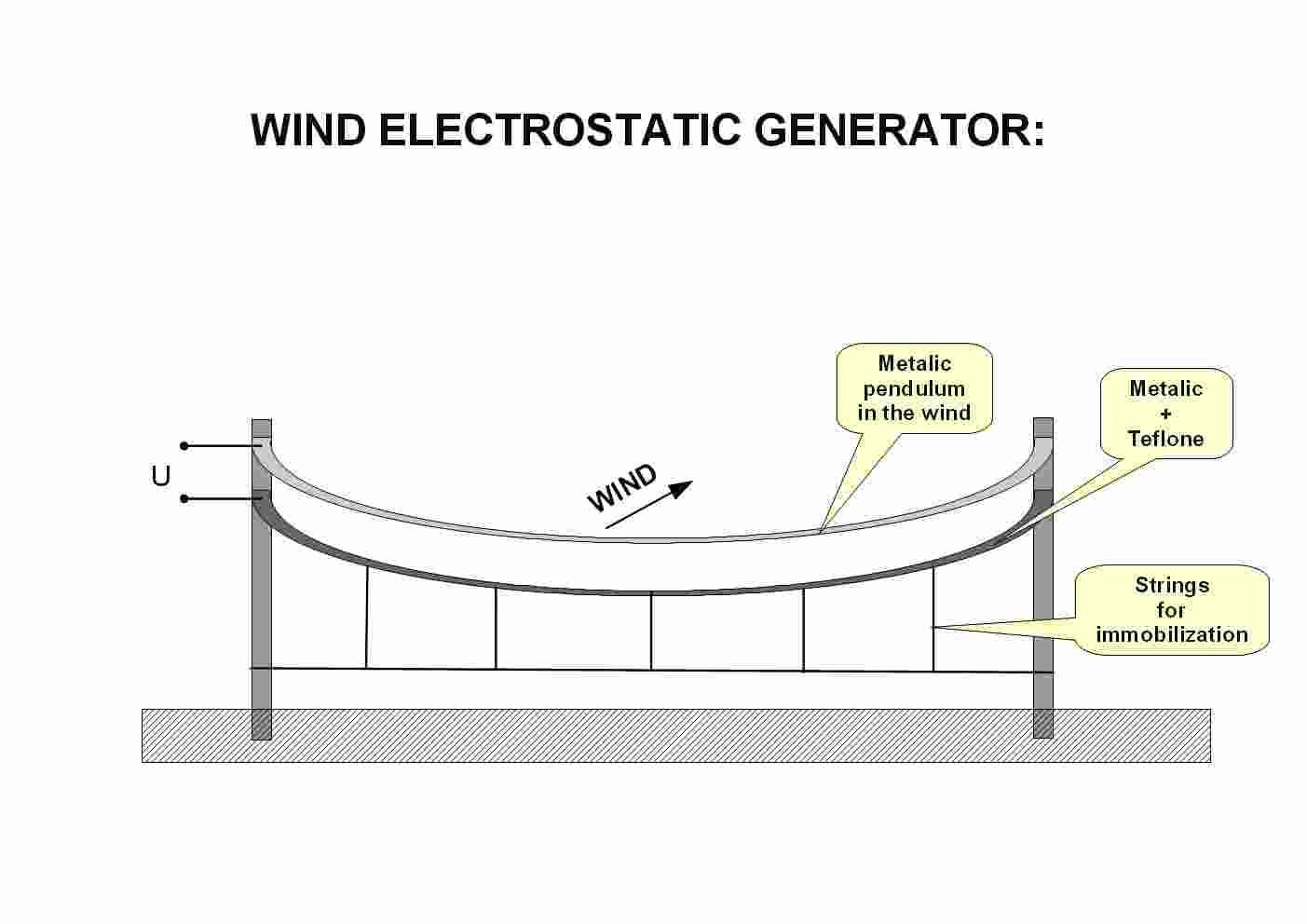
But, I think about some different device, where excitement is not in rays, but it is in wind form. If I have some wire with Teflon insulation, and it is fixed (with some strings) and can not move in any direction. If this wire is in ellipse form. Another wire in ellipse form can be upper of that insulated wire, but it can move like pendulum, this system on the wind will make some electricity between two wire. If that movement is enough, maybe constant sparking is possible. Some spiral form of Tesla coil can step down voltage after oscillation when spark occurred. This wire device can be changed to insulated long plate, where upper plate will oscillate like pendulum in the wind.
Maybe upper plate can work better if it is insulated with 'positive' material (like nylon). Teflon is definite the best solution for 'negative' insulation. I found some investigation on internet, where author talk about 'positive' air material error. Lot of books and tables think that air is best positive material. But he think that this thoughts has error, and it is not true. Too bad, because wind will electrify Teflon automatically. Author of that investigation think that only dust can make this effect. Humidity in air is enemy for this device, too.
Movement of ionization in air is like metallic movement, and this could be important part in Tesla's device. I think that air movement can be better source for energy. It is always around us. Question is how is the best way for collecting energy from changing distance (capacity) between two wires, plates or so. If this two metallic material go up and down voltage will be zero. It need discharge when is up and discharge when is down for work. Left/right too, because relative changing capacity is important here.
Spark can be use only after transforming to oscillation, because spark is enemy of diode rectifier. It is important to know that. After spark discharge through coil, it is easy to rectify with diodes, when voltage going down. All of this, and capacitor maximum voltage, must be consider, if something useful we try to build.
.
.
.
.
.
.
.
.
.
.
.
.
.
.
.
.
.
.
.
.
.
.
.
.
.
.
.
.
.
.
.
.
.
.
.
.
.
.
.
.
.
.
ROTATING SPARK GENERATOR (WORKING DEVICE):
This is my new spark generator, but in rotating form. It work very nice, and on every rotation it give two spark.
It is build from two part: static (not moving) part which is from teflone material. Rotating part is from some plastic, and important is aluminum foil on it. This is like upper electrophorus device, but cut in the middle (and make 'sandwich' form), and make upper plate in rotating form. On this rotating plate foil is divide in two electric part. This foil are not connected in the middle of plastic rotation plate.
Every time, when one part of rotating plate going up, it must have sparking discharge, and opposite plate, must have another discharge too. Half of rotating circle have positive teflone 'sandwich' in which this rotating plate with aluminum coating come in and out, two time in one rotation.
I am testing this device with 'stirodur' material, and with 30 cm diameter make 3 mm spark in every rotation (two of them). Teflone is material of choice, but I did not use this material yet. Problem is with first charging of teflone plate. It must be possible to easy remove this 'sandwich' teflone plates, charge them with some clout and hand rubbing. It is only for start. My device make spark 1 day after that. But if some ionization is around, this plates will need another rubbing.
Of course, collecting of this sparking energy can be in HF form, because it will be easy make Tesla's transformer discharge. Some glass capacitor will collect this spark energy too. I don't know how much energy this device need for continuous rotation, and how much energy will make, but in this form, wind can make rotation too, because one half of rotation plate can be closed for wind and another is not. More than one of this device can be on the same shaft. Only problem is how to start charging of teflone without remove plates. Maybe with some static positive electrostatic form of electricity with outside touching?
Be careful if you build this device in bigger form, because spark is electro-static, but can become dangerous.
I investigate methods of charging Teflon without rubbing. It lead me to old well know properties of dielectric material called electret. It is like permanent magnet, but in electric field form. Some microphone, dust filters... use it.
Creation of electret is simple (is it?). Insulation must be heat near melting point, and than it must be charge with DC electric field, and with this field around it need cooling process. If this material is Teflon, after field is disconnect, material became electret (it stay charged for long time, years). I found some measurement of 'electric life' for Teflon, and for 50% of losing charge with PTFE is around 14 years, and another form of Teflon (FEP) has 68 years for this 'half life' discharging.
I found on internet some ideas, where wire with insulation is heating in oven, and after DC current treatment and cooling, it became with electret properties. If this wire is in air, author claim of static generation in wind condition (vibration) because air has some ions around.
After all this thoughts and experiments, my understanding for Tesla's work on 'plates in the air' generator are more clearly. He talk about insulation on plate. Is it possible that it need electret insolation? Maybe, when insolation is put in liquid form on plate, it need DC field with cooling process, for become electret?
But my form of generator need some form of electret Teflon plates for work without rubbing. I have felling that here is the way to go for understanding this kind of electric machines based on static electricity...
Update thoughts about electret:
I found some interesting effect... After rubbing of some material it become electric. Air around it became electric too. If I put dielectric mesh on it, and thick foil with the same properties like first one (it can be rubbed too), this air stay in electric form after creation of that sandwich. Some glue around this system with good dielectric properties will prevent discharging.
Maybe electret system work like that... You must capture electrified atoms (electron) inside dielectric material, and it will stay electric for long time. Question is: how to easy put electric ions in some air bubbles or mesh (air inside mesh)? This is just an idea (I only try with plastic, mesh and glue-tape, and after more than week, paper probe has stick properties). If this will work, some sandwich system (foil + mesh + air) can possible create strong electric electret, after foil working electret is put in sandwich form.
.
.
.
.
.
.
.
.
.
.
.
.
.
.
.
.
.
.
.
.
.
.
.
.
.
.
.
.
.
.
.
.
.
.
.
.
.
.
.
.
.
.
ELECTRO-MAGNETIC GENERATOR WITH PIPE DESIGN:
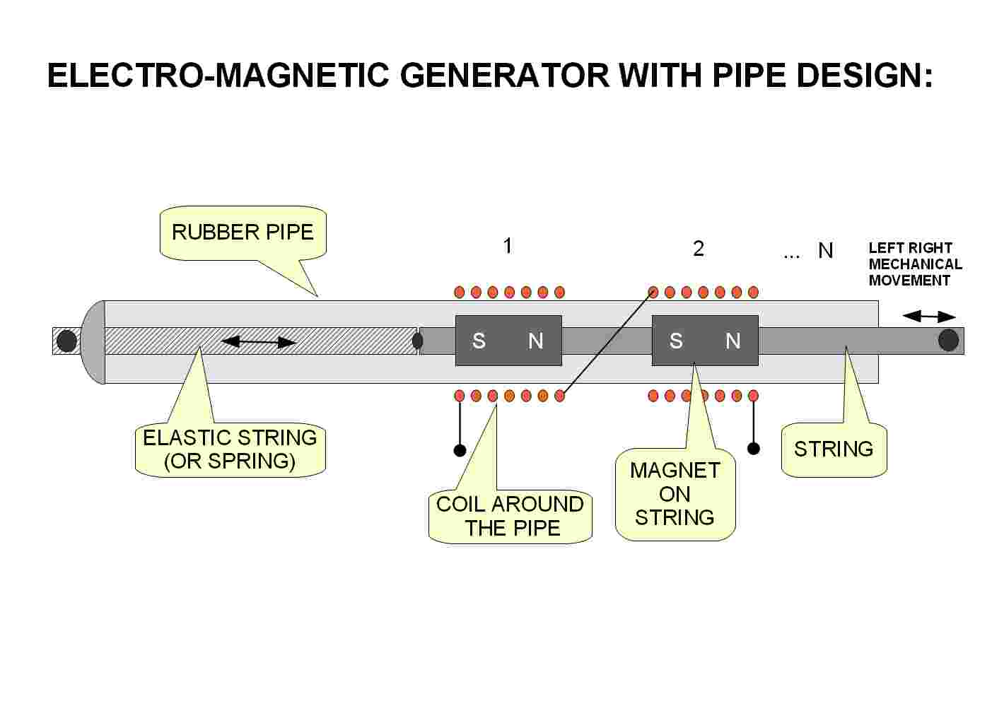
How can we collect energy of wind, from some tree branch movement, or something similar? This is idea with cheap parts. It is some plastic string inside the rubber pipe with lot of magnets on it. They are fixed with some glue or tape and every magnet has coil around rubber pipe. On one side it has elastic string (like for car fixing part). Mechanical movement between two branches, or with some wind vibration system, can create some energy with magnetic induction. Some diode can charge battery with this impulses. If coils are in series connection, magnets must be in the same direction, because of creation of current in that direction. If this kind of generator is fixed on both side, and if lot of this pipes are in vertical or horizontal formation, wind will create vibration and here will be "electric wind song". Coil wire must be isolated too, because of rain. I didn't try this device yet, but this idea look so simple to me.
.
.
.
.
.
.
.
.
.
.
.
.
.
.
.
.
.
.
.
.
.
.
.
.
.
.
.
.
.
.
.
.
.
.
.
.
.
.
.
.
.
.
UNLIMITED SOURCE OF CLEAN ENERGY:
In "Everyday Science and Mechanics", 1931. year, Tesla talk about possible source of energy from Earth temperature difference. He talk about ocean temperature difference with very hard pumping problem, and suggest of using ground tunel and tides for that purpose. Better way for thermal energy is using of grounding shaft with water and vacuum pump, because of natural lowering of water boiling point in wacuum. 1 km of shaft is good starting point. For cooling purpose some river or air can be usefull. Transmitting of energy can be wireless or standard system. It is unlimited source of thermal energy and oil drilling is all around the Earth and can be usefull. Using water-vacuum combination is easy way to transfer heat from ground. In this article, Tesla has thoughts about cosmic energy particle too, but in that time (1931.) it was not so great energy source (his words). Maybe in years after that, he found something better, but in this 1931. year, this thermal solution was best solution in his mind.

.
.
.
.
.
.
.
.
.
.
.
.
.
.
.
.
.
.
.
.
.
.
.
.
.
.
.
.
.
.
.
.
.
.
.
.
.
.
.
.
.
.
Where to find cheap battery solution for some solar system?
I found fact that solar cell are 10 time chipper than solar collector. But it must be inside homemade box. Main problem is creation of box for them. Because of that I think about roof tile box. Every roof tile can be solar system. One of solution is with standard roof tile (it need to be flat). I found tile with 10 tiles for 1 m2 of space. Every tile can have around 4 cells inside. You can create some edges and with silicone glue glass can be on it. Cells must not be glued directly to some material because shrinking can destroy the cell. But few point of silicone glue, can create flying cell. From roof tile can two wire going out. Between two roof tile connection must be rain resistant. Possible solution is with thermo plastic pipes. You just put plastic pipe into wire, and after connection just applay heat on that plastic shrinking material. I think about homemade roof tile with perlite material and aluminum concrete (2 days of drying). Glass must be with low part of ferrite (solar glass). I think that this kind of little collector is best option than big box version. Price of cells is around 1 $ per 1 W. 1 KW of cells can be around 1000 $. Only that boxing is problem. But it is good to know that it is around 10 time chipper than finished collectors on market.
I think about creating high frequency generator with every solar roof tile, but it will be more complicated. Than tile connection can be through one wire (some touching connection with two tile). But it need some oscillator inside each roof tile (one transistor...). And other part (battery bank) must have receiver of energy. It need experiment. It will be nice to have wireless solar cells system. When someone build big system, we must know that this system is live when Sun is here. It will be nice to have some black screen for cells glass. Diode for shading (Schottky) must be here to. High frequency transmitting through one wire will eliminate this problem too.
But I am writing this for battery bank, not solar cells...
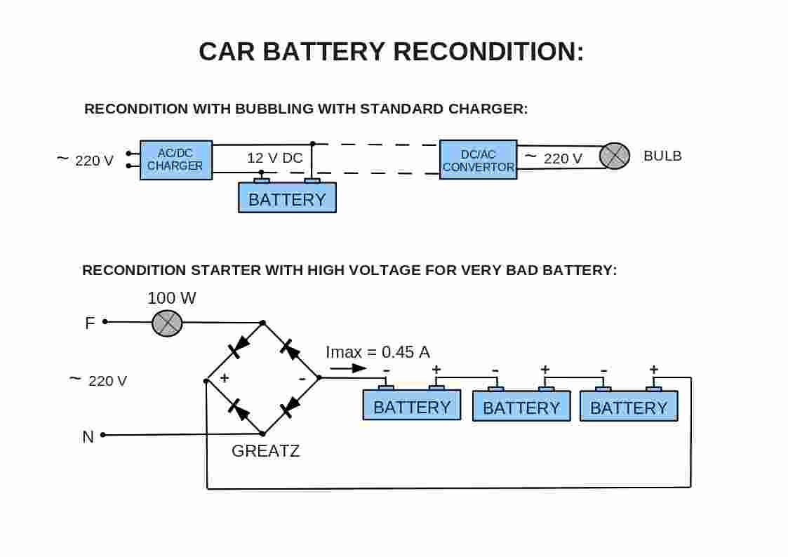
My investigation (based on lot of internet sources) found solution to recondition of car battery with high frequency impulses for charge the battery. It was too complicated system, but I was try this experiment with this solution. I see two main part here. First this HF impulses are allays in connection with diode (going to DC for charging). And it has voltage amplitudes (peaks). Yes it work after long time... I try to find why? Another recondition system has deal with adding chemical to acid solution. I don't like it, because it has side effect (short life of battery).
If we have old battery we have lot of PbSO4 inside two cells electrodes. Solution became like water and acidity is low. Always use glasses and gloves for protection. I recondition two battery (one 3 years after became bad for car, and one 5 years). One was sealed form, and I must cut plastic to see the solution inside. Another has standard cups (I like that more). I put distillate water in second one, because it was almost dry. I charge this two battery with standard cheap charger (8 Amp max), and after testing with inverter (300 W) and bulb (100 W), I have 30 minutes of energy with first battery and 5 minutes for second. It discharge with around 8 Amps (for 100 W). I like this real testing solution, because inverter has low battery protection between 10 and 11 Volts. I charge and discharge and so on. Every time I do that, more energy it can give. Why? But not always. Some time it was give very low energy bust. I found why... Time for charging did not add nothing. It is just put energy in good part of battery. This charging was around 4 Amps and going to 0.5 amps (or less). And here became interesting part... This low Amps can't add more energy (because PbSO4 is in strongest crystal form than standard). But it can electrolyze water. Oxygen has healing properties for cells, and it add more PbO2 to cell. For my charger it is around 4 minutes (with 100 W of testing) for one day. For regeneration of this two battery I will need around 2 month. Just sound of that bubbling is important. Cups must be open (I just put in close to them, because of dirty from air). Yes, before adding water, I clean that cups and holes with wet cloth (it is important to not add some dirt in battery solution, and not to use standard water).
After around 1 weeks, first battery from 30 minutes discharge (with 100W) become to 1 hour capacity, and another come from 5 minutes to 1 hour too, after 2 weeks. When they are come to that low Amps part and full of charge, and I can hear the bubbles, I connect both together in parallel, and put on the same charger. Voltage in that solution is around 15 V. This is why that HF peaks work. It not need HF current. It just need time to recreate cells. Every bubbling create more sponging on cells. For now I am on 8 Ah for each battery. I don't need battery for high current (car), but it will be nice to have cheap solar battery solution. Night energy is 50% cheaper than in day time. For this 8 Amps discharge, and 1 hour, if standard 100 W bulb will be replaced with energy saving lamp, it will be 5 time more light. I can't wait to see how much energy I can recreate. I discharge every few days, because this will preserve good part of PbSO4 crystal to stay in "easy" crystal form, and not became "hard" form. I think, this is the way for understanding this recondition. Buttery after 5 years is not dead, it is only in sleeping form.
But I have 3 battery with more than 5 years of not using. If battery is in this very bad condition, it can freeze if it is hold on low temperature. This will destroy cells (I think). I will never going inside battery (only with my mind) because of danger. One of three battery has two bad cells (my charger activate protection after 8 Amps of current). I connect 12 V (55 W) car bulb in series to limit that current, and charge this bad battery, and it hold charge, but voltage is around 9 Volts. I can hear bubbling when charging, and when discharging through that bulb too (of course, inverter can't start, because low voltage). But 12 V light bulb work fine. I will charge this battery on some different system, to see if that bad cells can be regenerated.
Another (more than 10 years) battery (I always add water if it need) don't charge nothing, when I put on standard charger (current is 0 with visual viewing on charger). Because of that bad battery, for experimental purposes, I create some 220 V charging station. I put in serial connection one 100 W bulb and Greatz rectifier (one diode is OK for half current). This is danger too! Maybe transformer with 50 Voltage before, will be better solution. I alway test with tester if battery are on no-light (no-phase) part, when I connect to 220 Voltage. I put in series three bad battery. One of them has 50 V on it. But this is going down to 15 Volts, and I can hear of bubbling. After disconnecting this charging and after 1 week of this low charge (0.35 Amps and wasting of energy on light bulb), one of battery became holding a charge (but very low). I test it with 5 W car bulb, and it has only few second of low light, and long period of red lighting (only wire inside bulb is red with low light). One battery is in worse condition, and Voltage just drop to 4 Voltage without red heat inside. Maybe some low energy light bulb will be better for testing, but I can't found around. I have good thoughts about that one which has voltage around 12 voltage before discharge. I need the time to see the power of bubbling...
If time of bad battery after not using is low, possibility of regeneration is very well. It is good to know that cheap battery can be found in car battery. Weight problem is not so big problem for home use. It will be nice to see how can bad solar battery (they replace battery every 5-10 years) will be after this recondition process. But I have not that kind of battery.
Update 1:
Bulb for limiting current can be replaced with capacitor for less wasted of energy. One thoughts come to my mind too... Capacitor move phase for 90°, and can recover imaginary part of inductive load on electrical network. Some virtual energy source? Is stealing when you help generator with capacity connection? I didn't test what electric meter write... (just a thoughts)
After three battery with success of recovery, and growing energy life (all three are now on more than 1 hour with 100 W discharge). Waiting time is only that I need for them, and possible adding water. I can see how this energy sponge suck water. Or maybe just heat create vapor.
But I have hard problem with one battery. It has 8 V on it. Two cells are dead. After some charging (I try with 55 W of bulb in serial connection with charger, because more than 8A and charger protection electronics), useful tester for density, can tell me which one of cell has problem. After marking of two cells, I close all other cells, and put some rubber plugs in holes for vent. After that I open only bad cells and suck acid with density tester to glass jar with plastic lid. Then I clean battery and put in big plastic container, and turn upside down battery. With rubber hammer I shake bad cells, because PbSO4 connection which short this cells are on bottom of cell. After cleaning, filtering of acid with coffee filter paper, I will reuse this acid again later. But not now. I get acid from another battery (which have 1 hour of life) from each cells a little, and put inside this two bad cells. I check other cells too, because some acid going out (possible some plug was not good). Using gloves and glasses is necessarily. Having fresh water and sodium bicarbonate for neutralization is important too. This part of experiments are only for brave and if someone know what can expect.
After this work I have 10 V on battery. And I charge it again. It hold charge and inverter with 100 W bulb work for 3 minutes. Charging current going from 8 A (with 8 V battery) to 4 A (with 10 V battery). I was thinking that both cells are good now, but I was wrong. Or maybe one cell was going to short connection after that 3 minutes of testing, because I charge again (half an hour of charging), and holding charge was going down (2 minutes). After overnight charging, I see differences in density tester, and I locate problematic cell. I was try another shocking with repeating that mechanical process. After second battery stress, I have around 12 V on battery, and first charging was hold 3 minutest on test. Second charging hold more energy, and battery has some breathing life. Just need time...
But another problem became visible... In that three buttery before (with easy recovering), I see that current (when charging) is around 4 A and going down, how it fill easy part of PbSO4 sponge, with going down to 0.5 A or less, when start electrolyzing of water (and this slow regeneration process). On this battery with two bad cells, after recover of cells, current stay on 2 A. This is not good, because good part of "sponge" is full (easy to fill that 3 minutes of starting charge). This means that some cells have some inter-cell connection resistor connection. I will charge this battery more times, and testing of growing capacity. Maybe this charging will disintegrate this "spark" of connections with acid. Because acid became stronger how I charge the battery with more energy. It is just theory. I try shock battery with few strong current from two serial connection with two battery (24 V). It is fear to listen strong electrolysis, and waiting for possible explosion (I try only three times with unknown current). But that 2A stay unchanged, and I will try only with charging. If that current will not going down, this battery will have fast auto discharge rate.
I have feeling that I more understand problem inside bad battery of this kind. It is important to start recovery immediately after battery rejection. My first three battery was not young. One of them was more than 5 years in basement, after rejection from car use (maybe 3 years of using). I think, it is good success...
If you check water, after first charging, can have around 12 V (all good cells), and very low current for electrolyzing, you can have good battery after around two month. Lot of that battery, can be connect in parallel, but only after first charging (when current will going to low). It will be good to have two charging station, one for initial charging and testing, and another with more connectors for energy capacity bust. My charger has around 15 V of output, when this recovery with electrolyzing start. Maybe bigger voltage will speed up this process, but possible stress for battery electrodes will put some crack on them. I think that in this parallel connection, on only one charger (chip one), you can have ten or more battery after two month of waiting (or less). It is important to control discharging each of them, because I don't know what will happen if we overcharge battery capacity. Maybe mesh structure of electrodes will became sponge too, and it will not have good mechanical properties, and it will drop to bottom of battery (like in too old one).
Good luck, and be careful... If I can buy nickel-zinc battery (Droom) in this world, I will not do this stuff. I don't talk about nickel-ferrite battery. I talk about nickel-zinc battery where zinc is inside steel mesh coating with nickel and chromium, with unlimited cycling possibility. I think, it is the best way than lithium technology. Maybe not in weight, but in combination of weight, price and duration of battery. With free wireless charging (wind protection or sun near road can create and send energy to car wirelessly). Is it not enough to pay a road traveling? If we want to have future, traveling energy must be clean and free. But it is not compatible to business thinking. Some people must to have money in the world that don't exist. More than I know about earth magnetic field and heat generator inside Earth, I am more sure about that. I can predict years of maximum earthquake for last 100 years. But, here is talking about reconditioning battery...
Update 2:
I try destroy dendrite with 24 V on every cell. Removing of acid from one cell, and than put current from two good battery (I use car help-starter cable, because I like to be on the other side of door). Few second of current and stop. After three time of shock, I move back electrolyte, and get out another cell, and repeat this process. I see something strange with third cell. It has black color in the electrolyte. This is not good. I filter it with coffee paper filter. It become little bright, but not like in other cells. I think, here is problem with that 2 A current. Maybe I will try with cleaning this cell with distilled water, but it is batter to come back to three good battery that I have. I have 6 battery, 3 of them are OK, one has this current problem, and another 2 are in very bad condition (around 5 V after some charging). Dendrite are metallic growing connection between two plate. It is main problem with this kind of battery. Easy way is get 50% of successful recovery, than try to solve this kind of problem. It is intentionally danger too. Maybe some chemistry for dissolve this dendrite will help, but if some plate is in bad mechanical state, it can be good start for future problem in some real using of battery.
Now is the question: How I can connect more battery together in parallel connection, but not only with wire, because every battery will 'communicate' with other? In that kind of connection every battery must be the same, with all good cells (if some cell become bad, it will discharge all other battery. If some big diode will be on battery output, it will automatically protect this battery system with different battery capacity. But diode has around 0.6 V of parasitic voltage, and with strong current (with 10 A is 6 W of energy on diode heat). Maybe some help with switching on battery in parallel connection with diodes (mechanical or mosfet)? Mosfet has low voltage in conducting state, but mosfet can be destroyed with low voltage on gate. Idea is to have enough battery system, immune on some battery problem, connected to inverter to have high voltage, for electric heat pump. Night electricity is 50% chipper than in day time. If heat pump have around 3 times more heat energy, it will (virtually) be 6 times (in price). Of course, this kind of battery are not for that kind of work, and they are not for deep discharge, but who knows. Maybe some high frequency converter, on each battery, and receiving point (diodes) for charging of lithium battery (phosphate-ferrite)? It will reduce size of lithium battery, but this kind of system will give strong current if system need... Every battery can be HF transmitter with different way of charging. More independent system. Night price energy supply, wind generator, solar cells, biomass-gas converter, heat to electricity converter. If some battery will going down, it just need replacement (with another revived).

Content is available under GNU Free Documentation